Sweeping K.I.T.T. Scanner Replica |
|
|
Who can really say they haven't, at some point, thought about the possibility of having a real K.I.T.T scanner on their car? Well I've always liked the idea anyway.
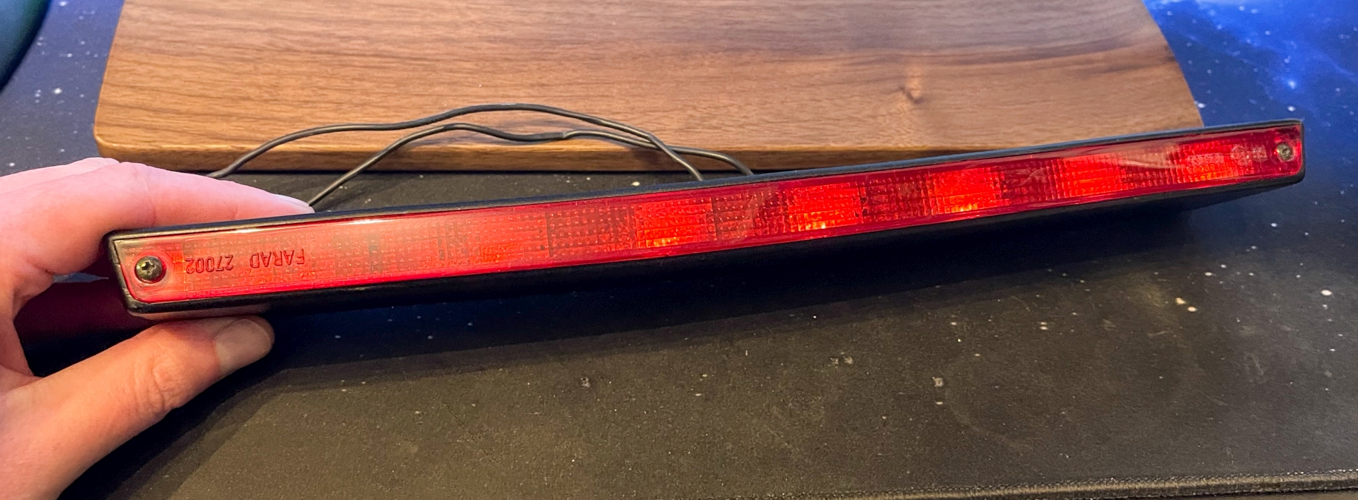
In 2014 a friend bought a cheap German BMW E30 Touring for our annual Nurburgring meet, because it was cheaper than renting a car and his company owned Focus was boring. Part of the reason for doing this was to strip some relatively rare parts and fit them to a loveling restored E30 Touring owned by another Slovenian friend. For some reason parts continued to be stripped off the car, including the aftermarket third brake light. I immediately saw potential and bought it. A Farad 27002 of mid-90s vintage, sporting 7 5-Watt bulbs. Not quite correct for an accurate K.I.T.T scanner, but close enough.
More than eight years later, I finally got around to actually doing something about it. I had been using Arduinos for years but it wasn't until 2023 that I felt I knew enough to get this to work.
First I stripped the light unit and removed the original cable. Thankfully every connection inside was made with spade connectors, so stripping it apart was easy. I could also leave the connections between the bulbs as I would be using them. I knew from the start that I would have to control each bulb individually, so to that I added a piece of 8-core trailer cable. Manufactured with one fat conductor as a common and seven smaller ones, it would be perfect. I laid these out to get the correct lengths before cutting, terminating and squashing them all back into a neat shape. The last common connector was connected to the fat white wire.
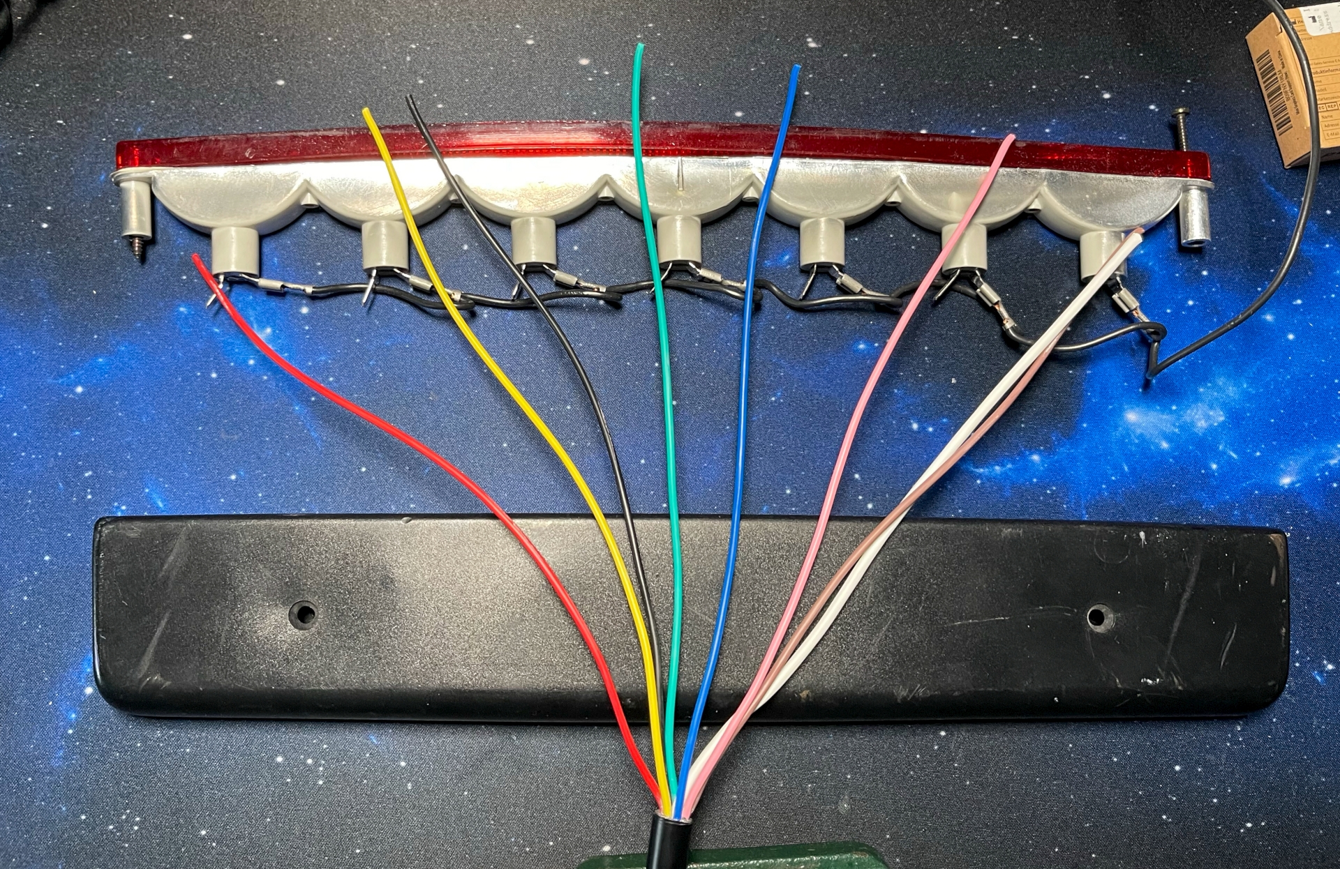


By supplying 12V to any coloured wire paired with the white, I could control one bulb.
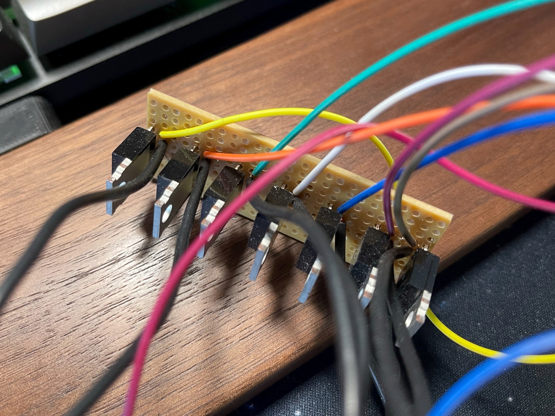
For controlling, an Arduino Micro and MOSFETS would be my method. I usually use the Ardunio clone Pro-Micro boards for all my projects, but they don't have enough PWM analogue pins for this, so I bought a proper branded Arduino. Two in fact, because during the project I let the smoke out of the first one. The MOSFETS I used were IRLZ34N N-channel, apparently capable of handling 30 Amps but I wasn't going to go anywhere near that for my 5W bulbs. These were laid out on a small piece of stripboard for testing, when I was happy I cut out a bigger piece, cut the tracks as necessary and soldered everything on. I'll come back to the code later with the specifics of building it.

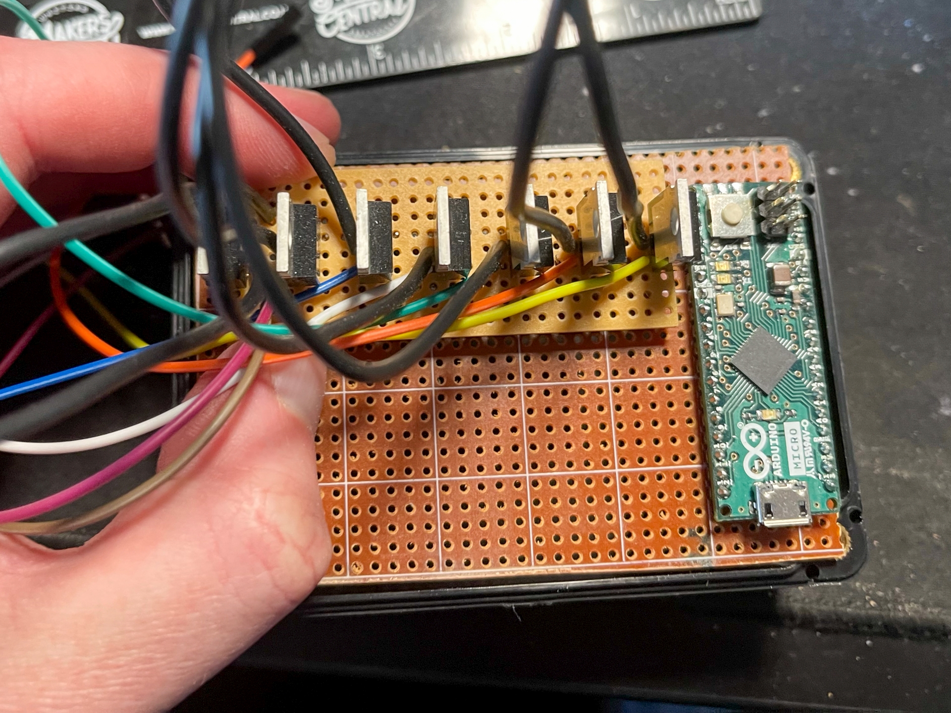
You might see that the image above has an area on the board marked "BATT". The original intention was to have a 9V battery inside the case at all times to power the scanner, and I wired the power up to a standard 9V battery connector so I could do this. The more I thought about it the more it seemed better to have a CTEK connector to connect to a car battery. I already had a CTEK connector on my bobtail Discovery for connecting the solar charger so this would be ideal. The only problem was 12V is too much for the Ardunio, so I had to introduce a DC-DC converter to drop the voltage to 9V, fine for the Arduino and still bright enough to power the bulbs. This thankfully fitted nicely into the same space the 9V battery would take.

During testing I found that I needed to add a capacitor between the ground legs of the MOSFETS and the Arduino ground. I can't fully remember why now, I think the procesor would keep crashing. 470uF proved to be ideal.

I added a switch and assembled the entire thing. With it working in July 2023, I kind of forgot about it until early 2024. Here are a couple of demo clips:
I had it installed and working on the bobtail during an event in early May 2024. I don't have any video of that but here's a photo I took while testing it.

Now to the specifics of the build. Here are the components I used:
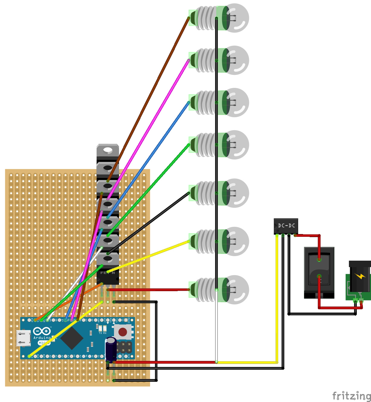
This is the schematic, followed by an approximation of the stripboard layout. These were both made using Fritzing, and the project file is available to download here. I didn't make this into a PCB within the software, but that could be done.
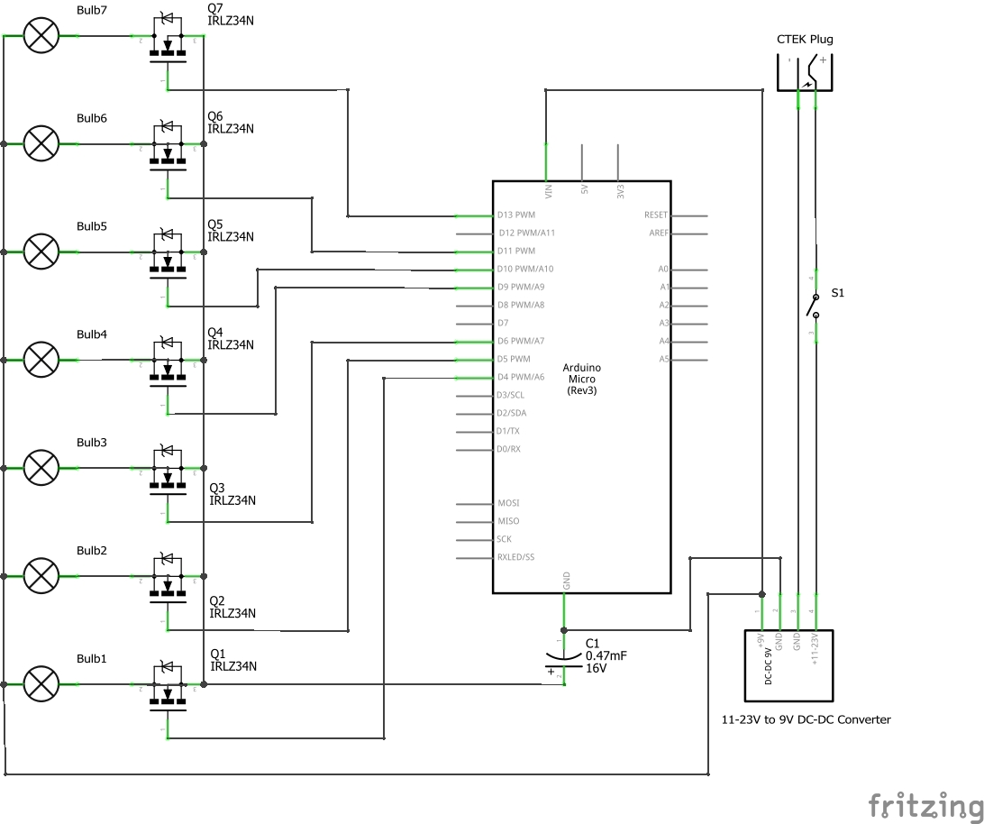
Wire colours on this aren't the best but they are accurate to my finished item. For example I had to use the white cable for +9V as it was the only thick cable of the 8 cores.
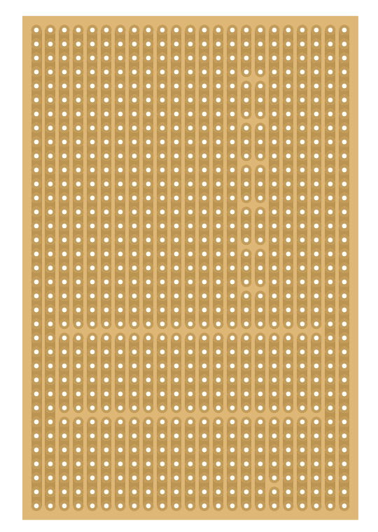
For reference, here is where the stripboard traces are broken:
The final code is based on that posted on the Arduino forum by user paul paulson, and it sequences each LED individually. His original code is available here
This is my modified version of the code to work with 7 segments:
//BLOCK COMMENT
// https://forum.arduino.cc/t/knight-rider-pwm/902477
#define ProjectName "Knight rider PWM"
// CONSTANT DEFINITION
// you may need to change these constants to your hardware and needs
constexpr byte Output_[] {3, 5, 6, 9, 10, 11, 13};
constexpr byte ledSeq[][sizeof(Output_)] {
{ 255 >> 0, 255 >> 2, 255 >> 3, 255 >> 4, 255 >> 5, 255 >> 4, 255 >> 7},
{ 255 >> 1, 255 >> 0, 255 >> 4, 255 >> 5, 255 >> 6, 255 >> 5, 255 >> 8},
{ 255 >> 2, 255 >> 1, 255 >> 0, 255 >> 6, 255 >> 7, 255 >> 6, 255 >> 8},
{ 255 >> 3, 255 >> 2, 255 >> 1, 255 >> 0, 255 >> 8, 255 >> 7, 255 >> 8},
{ 255 >> 4, 255 >> 3, 255 >> 2, 255 >> 1, 255 >> 0, 255 >> 8, 255 >> 8},
{ 255 >> 5, 255 >> 4, 255 >> 3, 255 >> 2, 255 >> 1, 255 >> 0, 255 >> 8},
{ 255 >> 6, 255 >> 5, 255 >> 4, 255 >> 3, 255 >> 2, 255 >> 1, 255 >> 0},
{ 255 >> 7, 255 >> 6, 255 >> 5, 255 >> 4, 255 >> 3, 255 >> 2, 255 >> 0},
{ 255 >> 8, 255 >> 7, 255 >> 6, 255 >> 5, 255 >> 4, 255 >> 0, 255 >> 1},
{ 255 >> 8, 255 >> 8, 255 >> 7, 255 >> 6, 255 >> 0, 255 >> 1, 255 >> 2},
{ 255 >> 8, 255 >> 8, 255 >> 8, 255 >> 0, 255 >> 1, 255 >> 2, 255 >> 3},
{ 255 >> 8, 255 >> 8, 255 >> 0, 255 >> 1, 255 >> 2, 255 >> 3, 255 >> 4},
{ 255 >> 8, 255 >> 0, 255 >> 1, 255 >> 2, 255 >> 3, 255 >> 4, 255 >> 5},
{ 255 >> 0, 255 >> 1, 255 >> 2, 255 >> 3, 255 >> 4, 255 >> 5, 255 >> 6},
};
// VARIABLE DECLARATION AND DEFINTION
unsigned long currentTime;
unsigned int sequence;
struct TIMER {
  unsigned long duration;
  unsigned long stamp;
};
TIMER blink_{160, 0};
// FUNCTIONS
bool checkTimer(TIMER & time_) {
  if (currentTime - time_.stamp >= time_.duration) {
    time_.stamp = currentTime;
    return true;
  } else return false;
}
void setup() {
  for (auto Output : Output_) pinMode(Output, OUTPUT);
  digitalWrite(3, HIGH);
  digitalWrite(5, HIGH);
  digitalWrite(6, HIGH);
  digitalWrite(9, HIGH);
  digitalWrite(10, HIGH);
  digitalWrite(11, HIGH);
  digitalWrite(13, HIGH);
  delay(3000);
  digitalWrite(3, LOW);
  digitalWrite(5, LOW);
  digitalWrite(6, LOW);
  digitalWrite(9, LOW);
  digitalWrite(10, LOW);
  digitalWrite(11, LOW);
  digitalWrite(13, LOW);
  delay(3000);
}
void loop () {
  currentTime = millis();
  if (checkTimer(blink_)) {
    int element = 0;
    for (auto led : Output_) analogWrite(led, ledSeq[sequence][element++]);
    sequence++;
    sequence = sequence % (sizeof(ledSeq) / sizeof(ledSeq[0]));
  }
}